Lego sorting machine
Note: this article describes a machine which is a work in progress. It is not complete. It currently does some interesting things, but it is not a fully-working, finished system. Unlike most of my other Technical Notes, this write-up is not a description of how to end up with a functional replica of my system at the end. However, I think you'll find it interesting all the same.
Lego
I started buying Lego (and/or getting my parents to buy it for me) around 1965, and I continued buying it until about 1980, when I took a bit of a break, went to university, and started work.
I started buying Lego again in the mid-1990s (around the time Mindstorms RCX came out), and I haven't stopped again since.
These days I buy nearly all of it on eBay, mostly second-hand, and sometimes as a "job lot" of several kilos of mixed parts. I estimate that I currently have around 80kg of unsorted Lego which was bought in that way.
I have little interest in building standard Lego sets; I prefer instead to create my own designs for things which are at least in some way useful (they perform an identifiably worthwhile task), and are generally quite large.
Sorting machines
One of the projects I've been working on (very part-time) since early 2015 is a Lego sorting machine. That means both that it's a sorting machine built out of Lego, and it's a machine which sorts Lego.
It was inspired in part by a mostly-Lego-built sorting machine created by Akiyuki Kawaguchi who has posted several videos on Youtube of his Lego creations.
More recently (May 2017) I also came across a rather less-Lego-based design by Jacques Mattheij, whose aim is to sort fast and accurately, rather than trying to build the device itself from Lego (but then again, if, as he has, you have two tons of Lego (which I calculate to be around 8 cubic metres) in your garage and you want to sort it for sale, I guess accuracy and speed are more important than "I did it with Lego!").
Both of these designs use the OpenCV computer vision library as part of the identification process, as does my machine.
As Jacques Mattheij points out, working out how to identify Lego parts from square one is tedious, time-consuming and in fact not very accurate. If instead you can use machine learning, the process is almost certainly faster, and very much more accurate than a human could train the system to be.
Jacques has based his image recognition system on Keras, which is a Python wrapper built on top of Tensorflow. I've decided to try using Tensorflow directly, and I've also found another project using Tensorflow to identify Lego parts.
Another machine learning system to identify Lego bricks (although in this case, only six different types) is based on IBM's Watson cloud service, although this project looks to me more like someone mainly wanted to build a very large Lego set and attach a Raspberry Pi camera to it. It doesn't do a serious job of identifying standard mixed Lego parts (and because it's based on a cloud service, it's very slow).
Most recently (December 2019), I've come across Daniel West's design, which is *really* close to what I've been aiming for (except he obviously understands a lot more about machine learning than I do). He explains some of the technology behind it in a separate Youtube video and he also has two web pages with explanations of how it all fits together and some of the machine learning techniques behind it.
My design
Summary of my machine:
- it's constructed almost entirely† out of Lego
- pre-separated Lego parts can be dumped into a 4.5 litre capacity hopper
- Update late 2017: I've now build a Lego pneumatic-powered grab arm which can take parts from a *very* large container (up to 40 x 40 x 60 cm, which is 96 litres) and place them into the hopper, filling it until an ultrasound sensor indiactes there's enough Lego to be getting on with, and then repeating once the hopper starts to get empty.
- a steep conveyor carries the parts up from the hopper and drops them at a reasonably steady rate onto:
- a three-stage horizontal conveyor (slow, then medium, then fast) which separates the pieces spatially from each other
- the final stage drops the pieces (hopefully, by now, one at a time) onto a transparent plastic conveyor over a backlit viewing platform
- all the conveyors described so far are controlled by one Mindstorms NXT, communicating to a Linux PC by Bluetooth
- a camera mounted on a delta robot arm identifies the locations of pieces on the backlit platform, and then zooms in on each one to get a good resolution image of it
- the delta robot is controlled by a second NXT, also talking to the PC by Bluetooth
- the camera images are processed by the PC running a C program using the OpenCV library
- the PC commands the positioning of the delta robot, controls the speed of the conveyors, and performs part identification - currently from a database lookup, but soon to be enhanced by using Tensorflow
- the back-end MySQL database has parameters of ~15000 parts, compiled from various Lego part database websites
† a few parts are not Lego - the camera (a USB webcam), the conveyor belts (stretch bandage material), and the backlit viewing platform (an old laptop display backlight) - oh, and the table frame, of course.
Click on any of the pictures below to see them full size.
Main machine
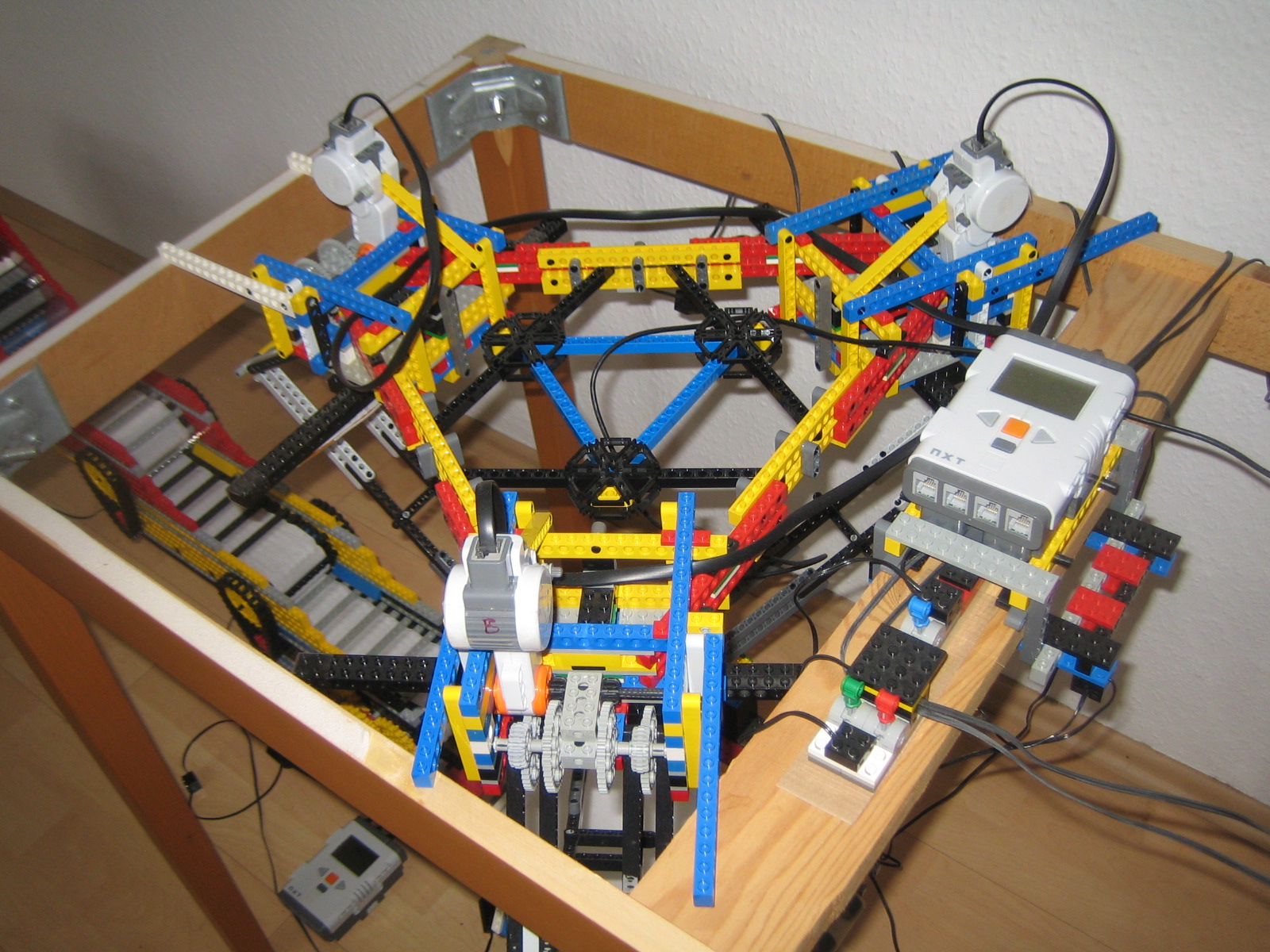
The main machine looks like this:
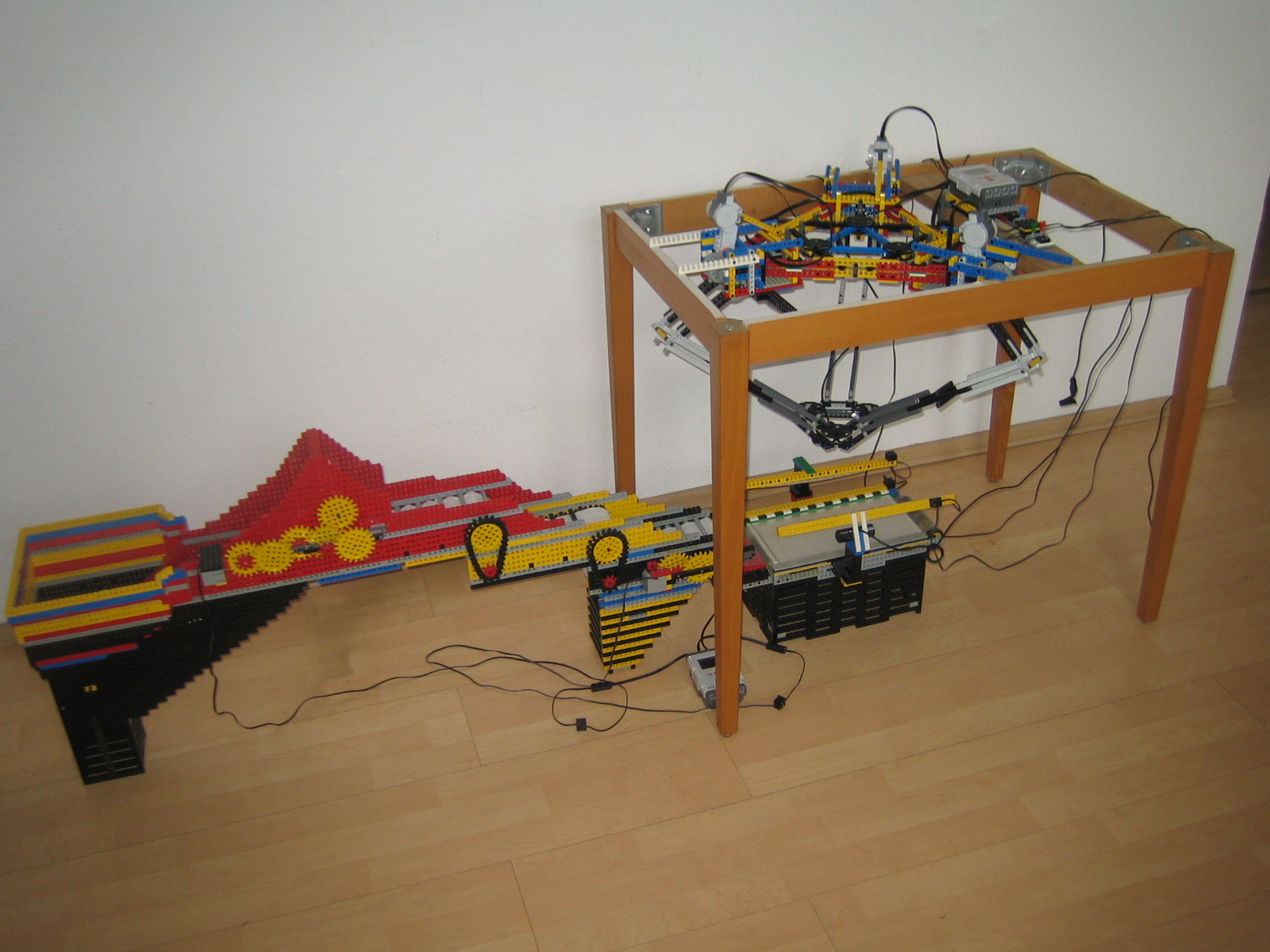
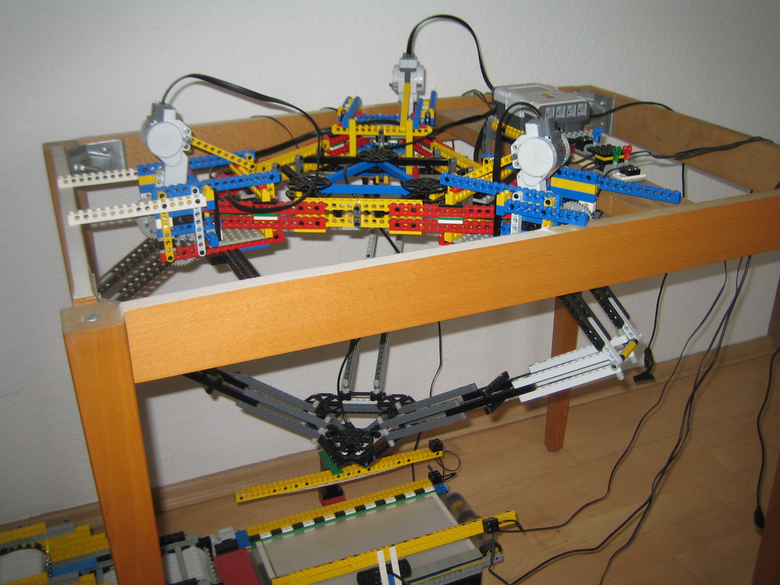
Most of the machine sits on the floor, but the delta robot hangs from the frame of a table (with the tabletop removed), and allows the camera to be moved around and zoomed in on different parts as they come in to view. Just for reference, the main conveyor system (the largely black, red and yellow Lego construction starting from the left-hand end, up to where it stops, just behind the foreground table leg in the above photo) is 115cm long, and 52cm high at the top of the red section; and the wooden table frame itself is 70cm high, 55cm wide and 85cm long. The viewing platform (the grey surface directly under the delta robot, details below) is based on an 11.6" (30cm) diagonal laptop display backlight, and is 17cm high.
I call this the "main machine" because:
- there's now a front-end loading system (not yet pictured) which can pick Lego parts from a box (which is bigger than the hopper) and put them into the hopper, thus eliminating the need for a human to periodically refill the hopper, and
- it needs (but doesn't yet have) a back-end mechanism for putting the sorted / identified parts somewhere - something is needed to take the identified parts and place them into separate containers (or, ideally, straight into the storage boxes I keep my Lego in). I don't know what this is going to be yet.
Hopper and first conveyor
The starting point is a hopper and a fairly steep upward conveyor belt:
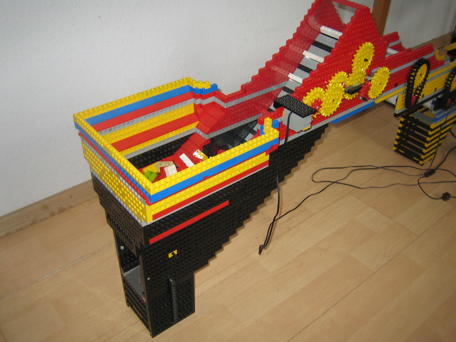
The 4.5 litre hopper looks like this (right, containing some standard 2x4 bricks):
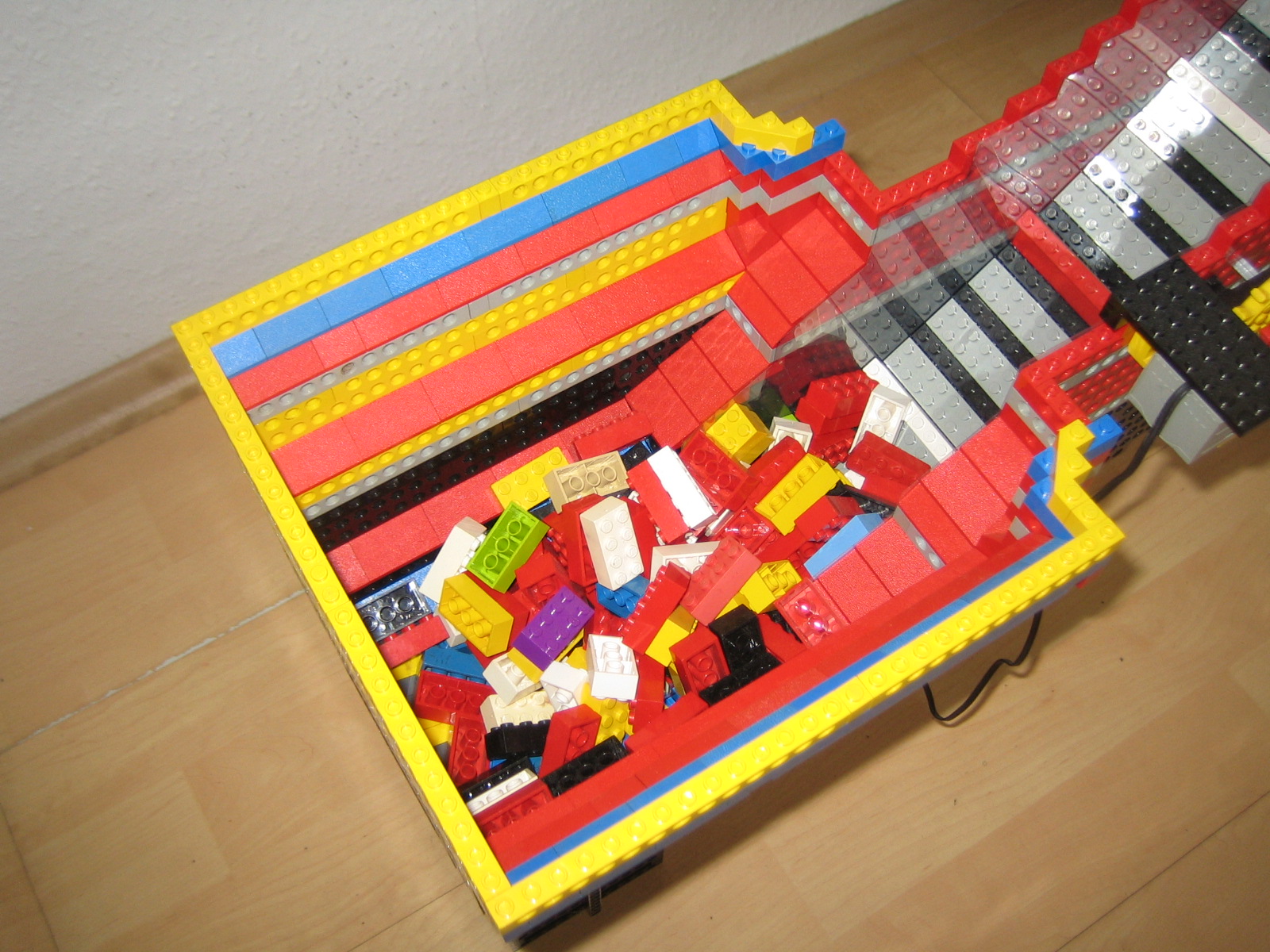
Note that you can see a strange reflection of the conveyor belt from the left-hand wall next to the belt going up to the right. This is because I built this section from Technic beams, which have holes in the sides (as you can more clearly see from the previous picture above), and this led to sharp corners on Lego pieces (large plates, especially) getting stuck in the holes, and jamming on the conveyor belt. To resolve this, I cut some clear plastic film and placed it on the inside walls of the conveyor area, so that the sides became smooth and the corners had nothing to catch on. I didn't have enough non-Technic beams to build the thing from smooth-sided Lego (although maybe I will have once I've sorted another 80kg of miscellaneous parts?).
3 horizontal conveyors
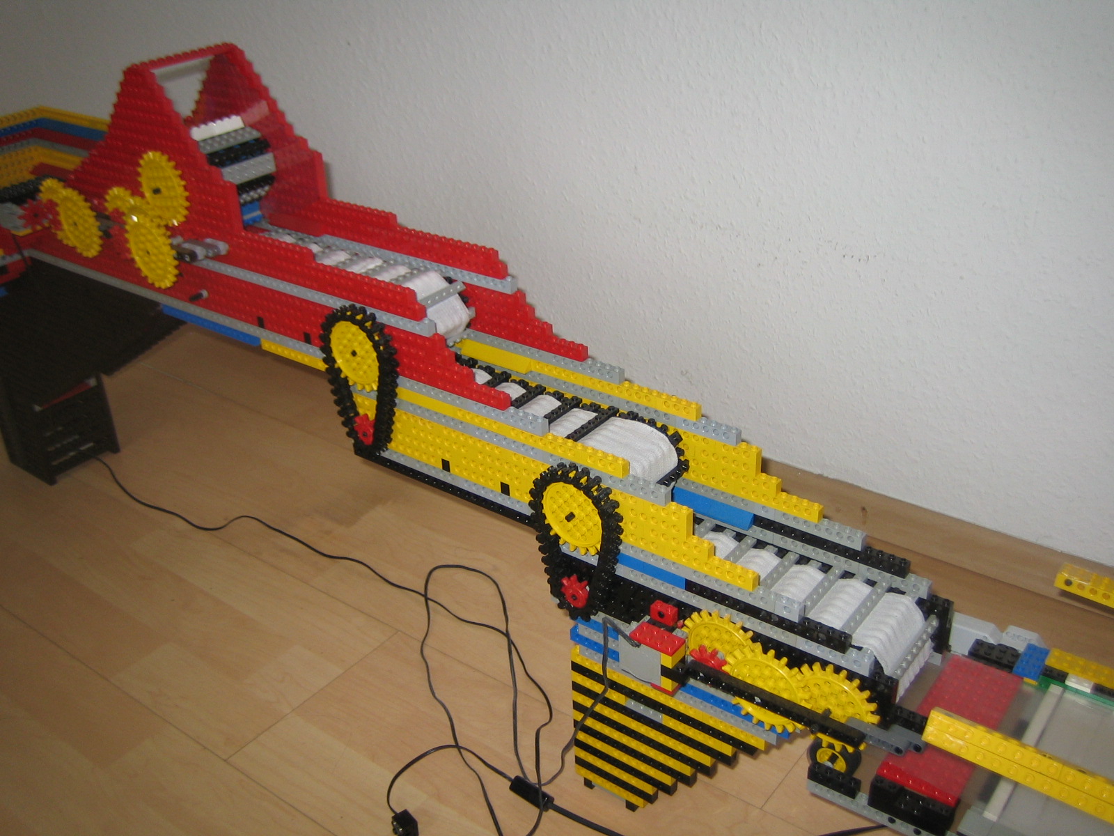 Following on from the upward conveyor (the steepness is deliberate, and lets excess pieces slide back down the steep slope, helping to separate the parts into a nice steady stream, instead of dumping large piles of Lego pieces all at once onto the next section of the mechanism) are three horizontal conveyors (the white surface of these is medical bandage material - just the right width, and with a rougher texture than can be achieved using pure Lego, preventing pieces from "bouncing" too much as they pass from one section to the next, or from slipping within each section). These conveyors are connected to each other using the red and yellow gears with the black chain-links, such that the first section (the highest, on the left) moves slowly, the second section (in the middle) moves a bit quicker, and the final section (lowest, on the right) moves fastest. This helps to separate the pieces even more, with the intention being that when they fall off the end of the third horizontal conveyor, only one piece at a time lands on the viewing platform.
Viewing platform
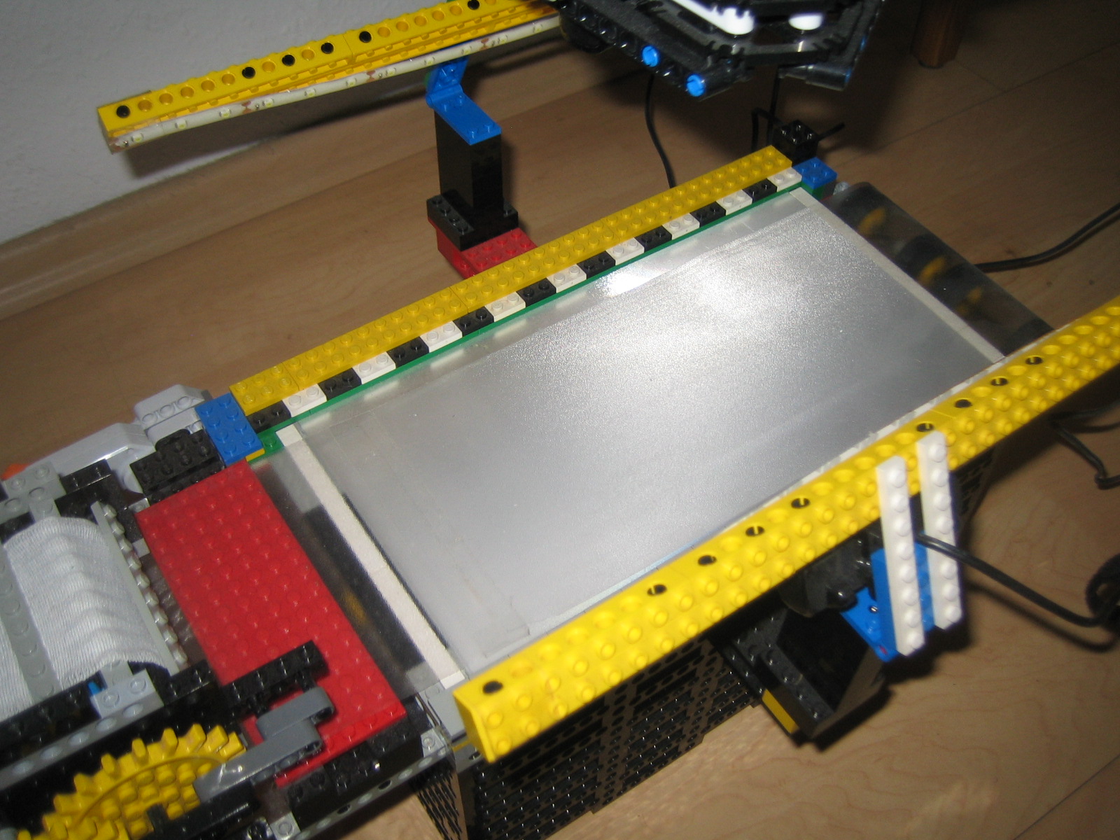 The viewing platform (right) is made from an old laptop backlight, with white LEDs (not visible in the pictures; they're built into the Lego framework behind and underneath the thin green strip) along one side to provide the sort of background illumination which you get on a laptop screen (laptop displays normally have no illumination actually behind the LCD screen; they achieve their brightness by having several very cleverly-engineered sheets of plastic film, one on top of another, which take light in on one edge, and diffuse it across the entire surface of the film, and direct it towards the front of the display. I'm pretty sure it's based on the same idea as a Fresnel lens, but it's part of what enables either fluorescent lamp or LED-based displays to be manufactured as thin as they are. Electro-luminescent displays are different. However, I digress…).
The viewing platform has a clear plastic conveyor belt running across it (you can see it best where it passes over the rollers at the right hand end), which allows the parts which drop off the end of the third horizontal conveyor belt, onto the large red plate visible at the left-hand end of the viewing platform, to pass underneath the camera, with backlighting, for identification. You can also see side illumination (the long yellow beams held together with black pegs have white-LED strips attached to the underside - you can clearly see these on the beam at the back), which helps to eliminate shadows around the parts, which could confuse the image recognition software.
Camera and delta robot
The main camera (there is a secondary one, which I'll discuss later) is mounted on the end of a delta robot (which I have to admit was one of the most fascinating parts of this entire system to put together, just on its own), which hangs from the table framework you can see in the first picture above.
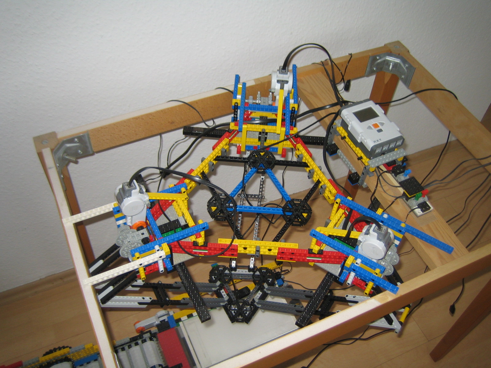
Here are some more detailed views of the delta robot, from above, from the side, and from below:
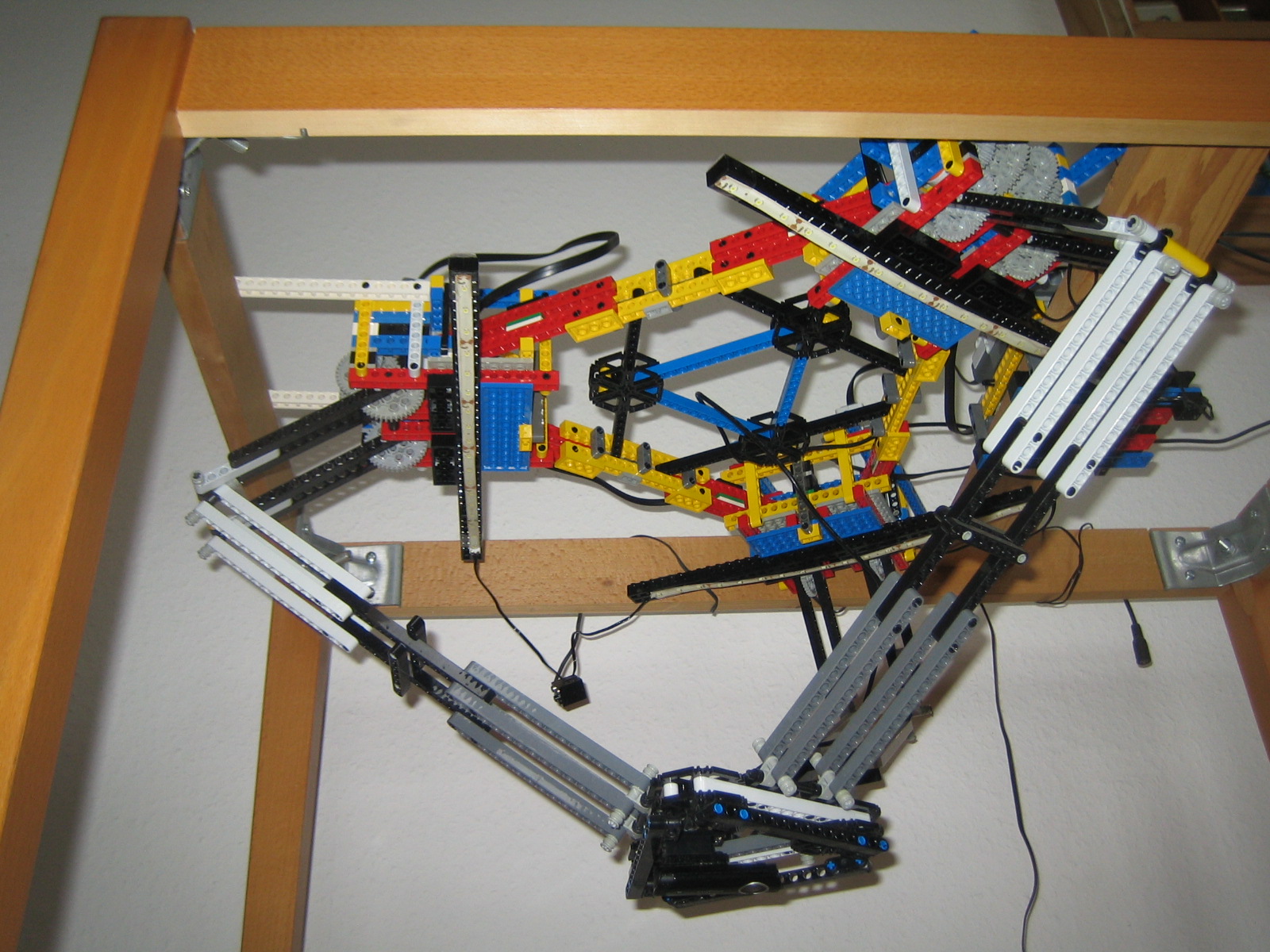
You can just see the circular silver lens-surround of the camera on the last image, from underneath the delta robot.
The robot is shown in approximately mid-way position - it's currently located over the centre of the viewing platform, and it can move the camera both higher and lower, as well as moving left/right and front/back, to get the camera centred over a Lego part almost anywhere on the surface of the platform, zoomed in on the part for optimal image size.
Illumination
Also on the view from underneath, you can see three more strips of white LEDs (mounted under the black beams attached under each of the three gear mechanisms), which provide illumination from above the camera, down onto the parts on the viewing platform. The intention of the three sources of illumination (above, below, and from the sides) is to get a good image of the top of the part, eliminate shadows as far as possible, and also to be able to identify holes in the part from the light shining through from the back-lit platform.
At present the illumination is controlled by the little blue, green and red switches you can see towards the right hand side (just below the Mindstorms NXT brick) of the "above" and "side" views of the delta robot above (and even better in the image below). I think the lighting ought really to be controlled by an NXT instead, but as a proof of concept, to make sure the imaging system works, I wanted convenient manual control of which lights were on and which were off, to be able to compare image quality under different conditions. (Also, the LED strips run off 12Vdc, whereas NXT output sockets only produce 9V, which makes the LEDs noticeably dimmer, so I'd have to organise some sort of 9V-to-12V switching mechanism for this to work.)
 Here's another overhead view of the delta robot, showing the Mindstorms NXT controller, the cables going to each of the three NXT motors, and the thin black USB cable from the camera, coming up out of the centre, between the three blue Technic beams joined together in a triangle (and, incidentally, coming up with a design for a rigid framework for this whole delta robot, based on 60° angles, was an interesting challenge using Lego, which generally doesn't "do" equilateral triangular shapes at all well).
Other bits
Not shown in these pictures is the desktop computer which the USB camera is plugged in to, nor are the power supplies for the two NXT bricks (I don't like running things like this from batteries, so both NXT controllers have the Lego rechargeable battery pack fitted, and which has a power input socket to be able to run them continuously from mains power).
Just visible at the very bottom centre of this picture, and attached to the end of the cable you can see bottom right in this picture (between the two thin white plates) is a second camera. This is intended to give a side view of the parts on the platform, and was put into the original design to give a measure of the height of the parts being viewed by the main overhead camera.
However, it turned out in practice that the software can calculate the height of a part under the main camera by measuring the parallax between a view from high up, and a view closer to the part, therefore this second camera has not been used in the image recognition so far. It might be used if the shape of a part as seen from the side turns out to be an important aspect of distinguishing certain parts from each other, but for the time being I'm simply working on the basis that ambiguously-shaped parts will be returned to the main input hopper, hopefully to be seen from a different angle by the camera on the next run (given that non-flat parts can land on the viewing platform on any of their sides, and either way up).
This parallax-based calculation is sufficiently accurate to be able to distinguish between a single plate (3.2mm thick, not counting the studs), two plates attached to each other (therefore 6.4mm thick) and a standard brick (9.6mm), simply by viewing them each from above from two different heights. I haven't yet tested to see whether it can distinguish between an upside-down studless tile (3.2mm thick) and a standard plate lying stud-side downwards (therefore 5.1mm thick), however given that the image recognition should be able to tell the difference between plates viewed from below, which have holes in the bottom of the studs, whereas tiles have only the circular "stud-catcher", as do the plates as well, I don't think this is an important feature to dwell on.
The imaging system
I've written further notes about the imaging system and how it works.
Software
There are a number of elements to the software in this thing. One day I intend to have notes about each of them here.
All of the code running on the Mindstorms NXT controllers is written in NXC.
The code running on the associated PC is written in C, using the Open CV library and accessing a MySQL database of parts.
- The conveyor system
- (which separates the parts and gets them to the viewing platform)
- The delta robot controller
- (which moves the camera to the required position)
- The camera positioning system
- (which tells the delta robot where to be)
- The object identification system
- (which picks the best match for the current part from the database of objects)
- The database of objects to be identified
- (which acts as the primary source of "this is what part XYZ looks like")
Go up
Return to main index.